ecentric Illumination: Why You Need It in Machine Vision Applications

Imaging and inspection projects require precision optical components and alignment to achieve optimal performance. These machine vision inspection applications utilize imaging lenses, illumination sources, cameras, and mechanics, to name a few key components. The choice of imaging lens and camera is integral to the success of an application; however, illumination plays a very important role as well. One of the most precise types of illumination geometry is ecentric illumination. What is ecentric illumination? How can it help achieve better results compared to standard backlight illumination? To answer these questions, consider illumination theory, benefits, and a real-world inspection application.
ecentric Illumination Theory
In optics, ecentricity is a unique property of certain multi-element lens designs in which the chief rays are collimated and parallel to the optical axis in image and/or object space (Figure 1). A key characteristic of ecentricity, then, is constant magnification regardless of image and/or object location. ecentricity is classified in three ways: object-space, image-space, and double. For additional information and definitions, please read The Advantages of ecentricity.
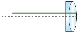
Figure 1: Example of ecentricity Where Chief Rays are Parallel to Optical Axis
In illumination, the concept in which chief rays are collimated and parallel to the optical axis applies as well. This is the case with a ecentric illuminator, sometimes called a collimated backlight. A ecentric illuminator, such as the TECHSPEC® ecentric Backlight Illuminator, uses optics to direct light from a fiber optic light guide or LED onto an object under inspection, producing a high contrast silhouette. A ecentric illuminator increases edge contrast and measurement accuracy by decreasing diffuse reflections from the object. Collimated light rays exit the illuminator and remain collimated as they strike an object’s surface (Figure 2a). In contrast, light rays from a standard backlight expand and interfere with one another, producing diffuse reflections (Figure 2b). For instructional examples, please view Imaging Lab Module 2.2: ecentricity.
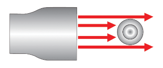
Figure 2a: Collimated Light Rays from a ecentric Illuminator
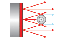
Figure 2b: Diffuse Reflections from a Standard Backlight
How Does ecentric Illumination Create a High Contrast Silhouette?
ecentric illuminators work by employing high-quality glass optical lenses to collimate light from a fiber optic light guide or LED spotlight. Divergent light from the source enters the multi-element assembly, becoming parallel and, thus, highly concentrated as it exists. Nearly all light that enters the ecentric illuminator (neglecting back reflection and absorption through each optical lens) strikes the object under inspection. In addition, many ecentric illuminators come with irises to control the intensity of the supplied illumination.
What is the Secret to ecentric Illumination?
When combined with a LED pattern projector and a reticle, a standard ecentric imaging lens can be used as a ecentric illuminator. As with a typical ecentric illuminator, light passing through the ecentric imaging lens is collimated, eliminating diffuse reflections when silhouetting an object. Unlike a ecentric illuminator, though, imperfections on the LED projector may be detected when using a ecentric imaging lens.
BENEFITS OF ECENTRIC ILLUMINATION
ecentric illumination is ideal for precision measurements where accuracy, repeatability, and throughput are key factors in an application’s success. To achieve the best results, consider eight key benefits of ecentric illumination.
Superior detection of small defects
Increased measurement accuracy and repeatability compared to standard backlight illumination
Elimination of blurred edges caused by diffuse reflections
Increased light intensity from collimated light rays
High contrast images from elimination of blurred edges and increased light intensity
Reduced camera exposure times from increased light intensity
Faster systems and higher throughput compared to standard backlight illumination
Increased distance between object and illumination source
APPLICATION EXAMPLE
Understanding the theoretical framework of ecentric illumination is a great first step. Next is analyzing a real-world application of this precision illumination geometry to understand why it is needed in machine vision applications. The benefits of ecentric illumination are ideal for a range of applications including high-speed imaging, factory automation, silhouetting, and defect and edge detection.
One example to explore in detail is the measurement and inspection of thread diameters on a stainless steel post. The small size of the objects under inspection (10mm), and the need to measure thread pitch, prohibited visual sorting. The original system employed for this application included a diffuse LED backlight in front of #56-678 0.6X TECHSPEC® SilverTL™ ecentric Lens on a 640 x 480 pixel CCD camera. A picking robot moved parts from the manufacturing turntable to the vision system for image acquisition. A second picking robot then used the collected information from the acquisition to designate parts into pass or fail bins.
Although well-designed, the standard backlight system could not inspect parts smaller than 10mm and was limited to 10ppm, whereas 40ppm was required to keep up with new production flow. In addition, the low light intensity produced from the diffuse LED backlight necessitated a 2.5ms camera exposure time; new production-line speeds allowed only 800μsec for blur free image capture. One simple fix was to increase the camera’s gain setting to decrease exposure time. However, this increased the signal-to-noise ratio in the system, decreasing measurement accuracy.
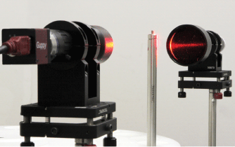
Figure 3a: ecentric Illuminator System Imaging Thread Diameters on a Post
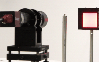
Figure 3b: Standard Backlight System Imaging Thread Diameters on a Post
The answer became clear – ecentric illumination! By replacing the diffuse LED backlight with #62-760 TECHSPEC® ecentric Backlight Illuminator, the intensity of the light striking the threads increased, reducing the camera’s exposure time and increasing overall image contrast by reducing diffuse reflections. Figures 3a – 3b compare the ecentric illumination system to the standard backlight system. Notice how the mechanical setups are nearly identical with minor modifications.

Figure 4a: Clear Edge Silhouette from ecentric Illuminator System
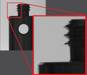
Figure 4b: Blurry Edges from Standard Backlight System
In the original setup, the diffuse reflections from the backlight created blurry edges. After substituting the ecentric illuminator, the edges became clear and much easier to determine if they passed or failed inspection (Figures 4a – 4b). Also, the burr on one side of the thread was barely visible with the standard backlight, but it is easy to detect and measure with the ecentric illuminator. From a technical standpoint, the graphs in Figures – 5b illustrate the contrast values of the ecentric illuminator system and the standard backlight system. The wider wells in Figure indicate higher contrast, resulting in improved measurement accuracy.
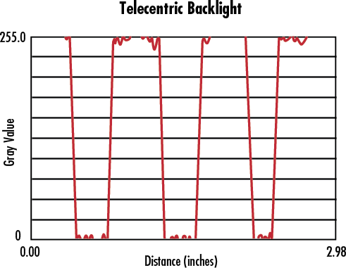
Figure : High Contrast Levels Using ecentric Illuminator System
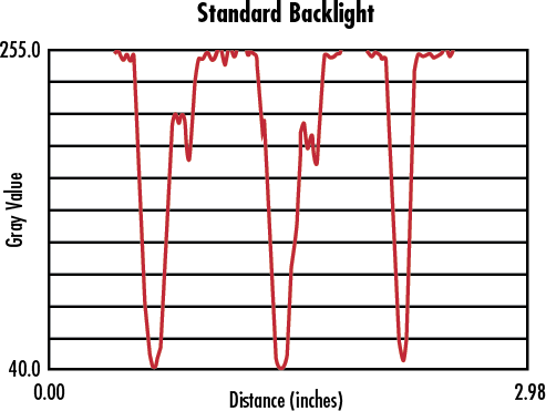
Figure 5b: Contrast Levels Using Standard Backlight System
ecentric illumination is beneficial for a range of machine vision applications. Unlike standard backlights, using ecentric illumination creates clear silhouettes, ideal for detecting edges and defects. The benefits of using ecentric illumination are crucial for applications requiring high contrast images that are free of blurred edges, and for high speed automation.
版权所有 © 2026 江阴韵翔光电技术有限公司 备案号:苏ICP备16003332号-1 技术支持:化工仪器网 管理登陆 GoogleSitemap